Magnetic field and magnetic flux
As we already know, magnetic phenomena can be described using a time-dependent field extended in space. We will denote this field by the letter B.
Since the field is extended in space we can actually restrict ourselves to a certain surface and only consider the effect of the magnetic field. As we will see in the following section, Faraday's law concerns magnetic fluxes, so we now present its definition for the case of a uniform magnetic field.
The magnetic flux is the amount of magnetic field that crosses perpendicular to a certain surface.
The magnetic flux can be computed as follows:
\[\Phi = \vec{B} \cdot \vec{A} = |\vec{B}| \cdot |\vec{A}| \cdot \cos(\theta)\]
Here, the dot indicates a scalar product and the vector A carries the value of a certain area and is directed in the direction of the normal vector of the surface. The symbol | | indicates the modulus of the vector and θ represents the angle between the normal vector and the magnetic field vector. See the image below for clarification:

Orientation-dependent magnetic flux through a flat surface. www.physicsbootcamp.org
In complex settings, the magnetic field is not uniform and the surface is not flat (which leads to the use of integrals and characterisations that are out of the scope of this article). We will only consider flat surfaces and uniform magnetic fields. This will result in a dependence of the magnetic flux on the angle between the magnetic field and the surface.
Faraday's law
Faraday's law is an experimental law that was later mathematically formalised and incorporated as part of what we now know as Maxwell's laws. It relates a concept from the electric field, the potential difference, with magnetic flux.
In particular, it relates the electromotive force (EMF) to the rate of change of magnetic flux. The electromotive force is the energy needed per unit of charge to establish a certain electric potential difference between two points and is usually denoted by the letter ε.
The mathematical description of Faraday's law is:
\[\varepsilon = - \frac{d \phi}{dt}\]
where there is a derivation with respect to the time of the flux. Although this description is very general, if we restrict ourselves to the aforementioned case of uniform magnetic field and a fixed area, we arrive, due to the expression of the scalar product, at the following equation:
\[\varepsilon = \omega \cdot |\vec{B}| \cdot |\vec{A}| \cdot \sin(\theta)\]
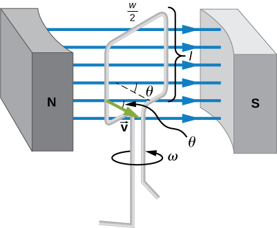
where ω is the angular velocity of the changing angle. The image below is an experimental setup for producing an electromotive force using a certain moving surface and a uniform magnetic field.

Experimental set-up for Faraday's law. openpress.usask.ca
What is magnetic flux linkage?
The equations that govern the behaviour of the electromagnetic field (Maxwell's laws) are linear, which means that we can consider the superposition of different fields that fulfill the same equations. If we are considering an experimental setup that generates an electromotive force, a simple quantity can help in increasing the output of electromotive force; this is what we call linkage. The magnetic flux linkage is measured in units of Webers \(\mathrm{Wb}\) just like magnetic flux.
Experimental setting of magnetic flux linkage
Imagine the setting we had before: a coil rotating in the presence of a magnetic field. The variation of magnetic flux induces an electromotive force. If we now take the same setting with N coils, we can create N different surfaces so the electromotive force is multiplied by a factor of N. This is what we call flux linkage.
Mathematical description of magnetic flux linkage
The mathematical description of flux linkage is based on Faraday's law. Again, since we are considering simple settings, we'll restrict ourselves to the case where we have N identical coils and this number remains constant. Furthermore, they are all synchronised and have the same three-dimensional orientation. This leads to the following increase of the flux:
\[\phi_L = N \cdot \phi \Rightarrow \varepsilon_L = N \cdot \varepsilon\]
where ϕL is the total magnetic flux linkage resulting from N coils and εL is the total electromotive force associated. Combining this with Faraday's law gives us the equation for magnetic flux linkage\[\phi_L=N\cdot|B|\cdot|A|\cdot\sin\left(\theta\right)\]
By doing this, we can manage to increase the potential difference with a simple addition of similar coils we can connect to the same circuit setup.
We are now going to consider several examples of experimental setups. The magnetic field present has a value of 10 Teslas, while the area of the coils we are using is 1 m2. We are rotating the coil with an angular velocity of 2 rad/s.
Imagine the magnetic field is directed in the x-axis, that is:
\(\vec{B} = (10,0,0)T\)
On the other hand, the normal vector evolves in the following way:
\(\vec{A} = (\cos(2 \cdot t), \sin(2 \cdot t), 0) m^2\)
where t is the time. This yields the following expression for the magnetic flux:
\(\phi = \vec{B} \cdot \vec{A} = 10 \cdot \cos(2 \cdot t) Wb\)
This allows us to easily compute:
\(\varepsilon = - \frac{d \phi}{dt} = - \frac{d}{dt} (10 \cdot \cos(2 \cdot t)) = 20 \cdot \sin(2 \cdot t) V\)
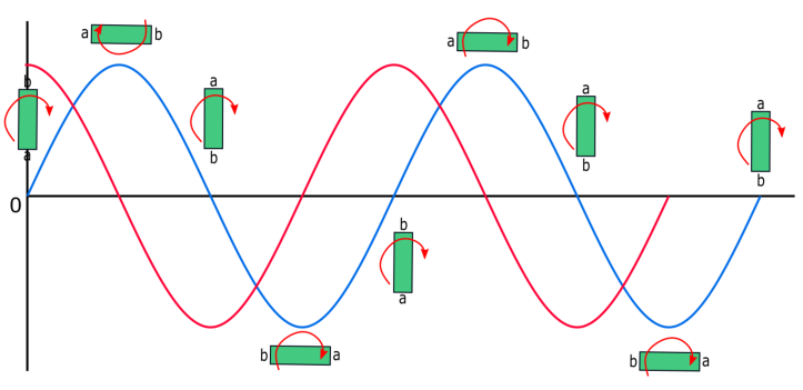
Below you will find a graph showing the time evolution of the magnetic flux and the generated electromotive force.

Temporal evolution of the magnetic flux (red) and the electromotive force (blue).
If we had managed to increase the magnetic field or make the surface of the coil bigger, we could also have generated an electromotive force, since we are varying the magnetic flux over time.
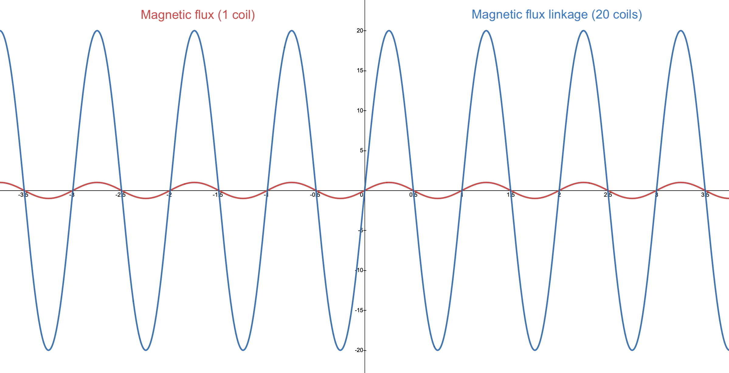
If we now consider 20 identical coils rotating synchronously, the graph of the time dependence for the magnetic flux density and the electromotive force would look like this:

Comparison between a set-up with 1 coil and with 20 coils. In the horizontal axis, time is represented and in the vertical axis, the electromotive force
We see here that the values of the total flux (and, then, of the EMF) have significantly grown by using only 19 extra coils.
We briefly turn to the case now for a static surface and a varying magnetic field. If now the field starts with an initial value of 0 Teslas, but continues to grow with time in the following manner:
\(\vec{B} = (10 \cdot t, 0,0) T\)
Consider a surface whose normal vector is:
\(\vec{A} = (1,0,0)m^2\)
We should arrive at the following expression for the magnetic flux:
\(\phi = \vec{B} \cdot \vec{A} = 10 \cdot t \space Wb\)
This expression's time derivative gives the expression for the electromotive force, that is:
\(\varepsilon = -\frac{d \phi}{dt} = - \frac{d}{dt}(10 \cdot t) = -10 \space V\)
It would generate a constant electromotive force between the extreme points of the coil. Of course, we could use several coils to build a magnetic flux linkage and increase the output.
In fact, when we use several coils, it is usual to vary the magnetic field and not the orientation to generate an electromotive force. This is the reason why we usually associate the concept of magnetic flux and Faraday's law with only one rotating coil, while the concept of flux linkage usually designates several static coils in the presence of a magnetic field.
Magnetic Flux and Magnetic Flux Linkage - Key takeaways
- Magnetic flux is a quantity that measures the amount of magnetic field crossing perpendicular to a certain surface.
- Faraday's law establishes a relationship between a force creating a difference in electromagnetic potential and the variation of magnetic flux over time.
- Faraday's law applies whenever at least one of these three varies over time: the intensity of the magnetic field, the area it goes through, or the orientation of the surface with respect to the field.
- The situation where there are several coils through which a magnetic field goes is called flux linkage. The flux increases proportionally.


